Task description
NOTHING YET
Summary of the week
Two embedded platforms to be tested
In this week assignment I did twofolded task: a) I did program my self-produced board, but also b) got familiar with successor of ESP32 (which is "heart" of my Finla project) ESP8266
Self-made PCB with button and..
this will be reported later on, because my strong interest is aligned to ESP platform
ESP32 and ESP8266 low-cost IoT-platform
I got ESP8266 to load from FabLab before Covid-19 isolation and at that time I thought that it were ESP32, newer version of ESP8266. I tried to program it with ESP32 settings and didn't get it working properly. I will explain these phases below
>Later on I understood that I had ESP8266. not ESP32 and I got my first program running: LED started to blink. ye! I was happy.
ESP32 and ESP8266: amazing IoT platform!
Actually we got Arduinos to be used at the home during Covid-19 isolation, but I did ask could I get also ESP32. I thought that it would be beneficial to learn to use it with different sensors and actuators, because my final project would rely on to it anyway.
My final project will be a part of bigger Alvin AI robotics project, where main group is trying to create robot arm. I am aiming at to remix their idea to car. Anyway, main unit in robot itself is ESP32 and that's why I knew it before embedded coding lesson and had internal interest to toy with it
That's why I had very strong interest to learn, how to program ESP32 NodeMCU, that I got from the univesity before Covid-19 closure. Or, actually, I thought that It would be ESP32, but it wasn't, in the reality I got ESP8266 from Fab Lab. I did learn it later, after long long long debuggin with my non-functional "ESP32"
What are the differences between ESP32 and ESP8266?
When I got ESP8266 instead of ESP32 from FabLab, there was no clear cues for amateur like me to recognize major differences. Later on I have learnt that modules are in somewhat compatible, but ESP32 is much much much more faster and has a lot of functionalities which are missing from the older ESP. For example, bluetooth, another core, support for touch sensors, GPIO lines etc. are missing from ESP2866. Table below gives detailed comparison between older and newer ESP modules (source for table: https://circuits4you.com/2019/03/02/esp32-vs-esp8266/)
| ESP32 | ESP8266 | |
| CPU | Xtensa Dual-Core 32-bit LX6 with 600 DMIPS | Xtensa Single-core 32-bit L106 |
| WiFi Speed | 802.11n up to 150 Mbps | Up to 72.2 Mbps |
| WiFi Protocol | 802.11 b/g/n (2.4 Ghz) | 802.11 b/g/n (2.4 Ghz) |
| GPIO | 36 | 17 |
| Bluetooth | YES | NO |
| DAC | Two 8-bit DAC Channels | NO |
| ADC | 12-Bit SAR | 10-Bit SAR |
| ADC Channels | 8 Channels | Single Channel |
| ADC Reference V | 1100mV | 1100mV |
| SPI/I2C/I2S/UART | 4/2/2/3 | 2/1/2/2 |
| WiFi Modes | Station/SoftAP/SoftAP+Station/P2P | Station/SoftAP/SoftAP+Station/P2P |
| Touch Sensor | YES (8-Channels) | NO |
| Temperature Sensor | YES | NO |
| Hall effect sensor | YES | NO |
| SRAM | 520 kB (8 kB of SRAM in RTC) | RAM size < 50 kB |
| FLASH (external) | 4Mbytes (also available higher) | 4Mbytes |
| ROM | 448 kB of ROM for booting and core functions | No programmable ROM |
| Network Protocols | IPv4, IPv6, SSL, TCP/UDP/HTTP/FTP/MQTT | IPv4, TCP/UDP/HTTP/MQTT |
| Peripheral Interface | UART/SDIO/SPI/I2C/I2S/IR Remote Control | UART/SDIO/SPI/I2C/I2S/IR Remote Control |
| GPIO/ADC/DAC/Touch/PWM/LED | GPIO/ADC/PWM/LED | |
| Operating Temperature Range | -40C ~ +85C | -40C ~ +125C |
| Operating Voltage | 2.5V ~ 3.6V | 2.5V ~ 3.6V |
| Operating Current | Average: 80 mA | Average value: 80 mA |
| Price | $4 - $10 | $3 - $6 |
What are ESP modules and What are ESP NodeMCUs?
Description of the ESP modules
The ESP32-PICO-D4 system in package module combines an ESP32 silicon chip, crystal oscillator, flash memory chip, filter capacitors, and RF matching links into a single 7 mm × 7 mm sized QFN package.
Furthermore, ESP32 based surface-mount printed circuit board modules directly contain the ESP32 SoC and are designed to be easily integrated onto other circuit boards.
For example, in the FabAcademy context, I will use this ESP32 module instead of ESP NodeMCU, because to use module I need to design circuitboard for it (which is one requirement in the final project of the Fab Academy)
See detailed description of the different ESP32 modules here: https://en.wikipedia.org/wiki/ESP32#QFN_packaged_chip_and_module
I had previous experience of using Linksys NSLU2, Raspberry Pi etc. as a platforms for data logging, centralised DVB-t tuner and have had several home automation systems, so I had already pretty much ideas for exploring the possible use cases of ESP32/ESP8266. Actually I was very exctied when I found integration between hass.io -home automation and ESP platform and even more excited when I found node red etc.
Some interesting links below:
- esphomelib - A comprehensive solution for using ESPs with Home Assistant: https://www.home-assistant.io/blog/2018/06/05/esphomelib/
- ESP8266 and Node-RED with MQTT (Publish and Subscribe) https://randomnerdtutorials.com/esp8266-and-node-red-with-mqtt/
ESP32 NodeMCU review
Installing ESP8266 Board in Arduino IDE
You need to a community created add-on for the Arduino IDE that allows ESP8266 to be programmed by using ARDUINO IDE and its programming languages
This section shows how to install ESP8266 board in Arduino IDE (compatible with Windows, Mac OSX or Linux)
Install ESP8266 add-on in Arduino IDE
Follow the images below and read guidelines below each picture
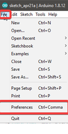
Figure: In your Arduino IDE, go to File> Preferences
.png)
Figure: Enter http://arduino.esp8266.com/stable/package_esp8266com_index.json into the “Additional Boards Manager URLs” field as shown in the figure below. Then, click the “OK” button:
if you already have configured e.g. ESP32 boards URL, you can separate the URLs with a comma as follows:
https://dl.espressif.com/dl/package_esp32_index.json, http://arduino.esp8266.com/stable/package_esp8266com_index.json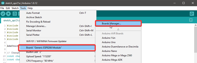
Figure: Open the Boards Manager in Arduino IDE: Go to Tools > Board > Boards Manager
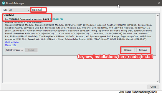
Figire: Search for ESP8266 and press install button for the “ESP8266 by ESP8266 Community. It should be installed immediately!
Testing the ESP8266 add-on installation with simple LED circuitry
To test the ESP8266 add-on installation, you need to build simple setup where we run short code on ESP8266 to blink LED lamp. Before coding anything, we need to build simple electronics by using LED and ESP8266. Parts required for this simple set-up are as it follows:
- ESP8266 NODEMCU board
- LED
- Resistor (330ohm)
- Breadboard
- Jumper wires
Schematic of the LED connections
In this phase you need to build very simple circuit, which will be controlled with the program on ESP8266. Connect an LED to your ESP8266, as shown in the following schematic diagrams. The LED should be connected to GPIO 2 (D4 on ESP8266) and equipped with resistor (which will prevent flow of overcurrent in some erranous use cases).
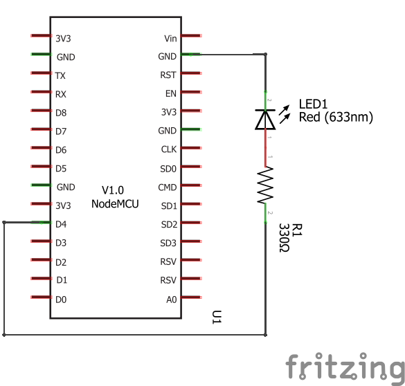
Figure: Schematics of the LED installation
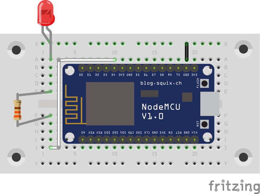
Figure: Schematics of the LED installation on breadboard
Creating the sketch (code) and uploading it to ESP8266
How to establish the connection between ESP8266 and arduino IDE
Because this documentation is based on ESP NodeMCU kit, uploading sketch is simple. NodeMCU has built-in programmer. Only thing needed is to plug board to computer and select right board from Arduino IDE
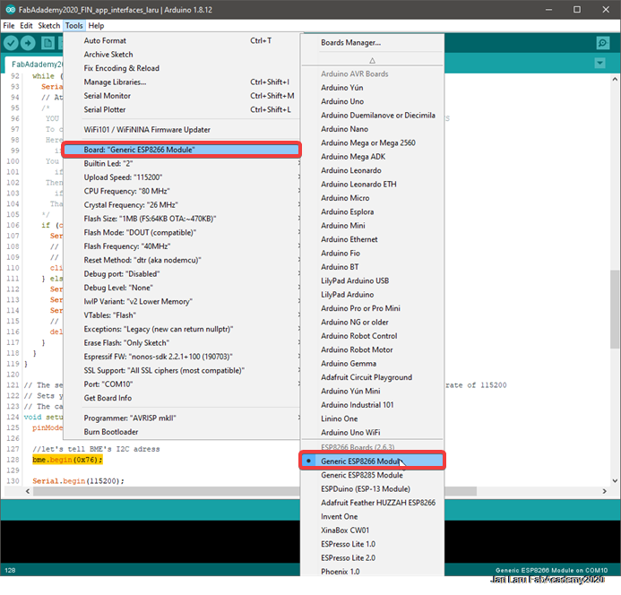
Figure: Choose ESP8266 board from the list
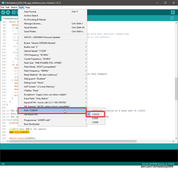
Figure: Choose correct COM port from the list
---- HERE ADD HOW TO KNOW WHERE PORT IS --
How to upload simple "LED blink sketch" to ESP8266
You can use the code below to put LED light blink. Code in this case is very simple:
			int pin = 2;

			void setup() {
			  // initialize GPIO 2 as an output.
			  pinMode(pin, OUTPUT);
			}

			// the loop function runs over and over again forever
			void loop() {
			  digitalWrite(pin, HIGH);   // turn the LED on (HIGH is the voltage level)
			  delay(1000);               // wait for a second
			  digitalWrite(pin, LOW);    // turn the LED off by making the voltage LOW
			  delay(1000);               // wait for a second
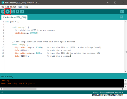
Figure: Click the arrow (upload) button in the Arduino IDE and wait a few seconds until you see the message “Done uploading.” in the bottom left corner. During this phase IDE will compile code compatible with ESP8266 and after that upload it via usb cable to ESP8266 NODEMCU
Wrapping up
So, I did ask Fab Lab staff that could I get one ESP32 to home, and they gave one from their inventory. Accidentally no one didn't check the ESP number, so I got actually ESP 8266. Because I am not so good expert with Arduino IDE, I tried to follow tutorials to upload simple code to ESP32, without success. Instead I got
https://circuits4you.com/2019/03/02/esp32-vs-esp8266/
https://electropeak.com/learn/getting-started-with-the-esp32/#The_ESP32_Module_Features
https://vaasa.hacklab.fi/2016/02/06/esp8266-on-nodemcu-board-ds18b20-arduinoide-thingspeak/
https://lastminuteengineers.com/multiple-ds18b20-esp8266-nodemcu-tutorial/
https://mechatronicsblog.com/nodemcu-programming-first-steps/
http://fabacademy.org/2020/labs/waag/students/hyejin-ahn/week13.html http://fabacademy.org/2020/labs/barcelona/students/benjamin-scott/week-12.html- Embedded programming: to get familiar with ESP32
- Input devices: to get familiar with reading sensors (temperature, ultrasound)
- Output devices: to get familiar of programming servos and motors
- Interface and application programming: Simple application which interfaces ESP32 via wi-fi. It will control servos/motors and read sensors. More complex program code may come to final project from Alvin Ai affordable project project members (so I will do only code for learning purposes)
- networking and communications: I will practise how to made wifi connection between ESP32 rednode and another device (might be Raspberry Pi with Hass.io homeautomation)
- Machine design: if possible, I try to build very first prototoype of the car with basic automation
- Wildcard week: maybe some constructions to project (structure to car)
Questions to be answered
What will it do?
My final project will be a remix project, where I will create a car by using same major components than is used in Alvin robot arm
Idea of the project (and other alvin AI projects ingeneral) is to teach school children to understand computational thinking, robotics, technology and other topics by using very low cost components and digital fabrication methods.
Design should be easy and affordable, that K-12 students would be able to purchase, build and use that robot car
Who's done what beforehand?
I will remix ideas of affordable Alvin AI project, so it's my main source of ideasThis project is a remix project for affordable robot arm project, which uses Alvin AI as a engine. So in practise, I will develop affordable car robot based on ESP32 microprosessor and Alvin AI. Car will be controlled by ESP32 which will get commands from mobile phone via wifi. Children will control the car by teaching artificial intelligence via Alvin AI.
Alvin AI will use machine vision (by using mobile phone camera), student operations and sensor on car robot for controlling movements (to give commands to ESP32 on car via wifi)
Earlier Fab Academy project, which I will use as a starting point:- I will also remix the ideas of final project by Heidi Hartikainen (Fab Academy 2018, from Oulu)
What will you design?
I will design three-four wheeled robot car, which has holder for mobile phone, ESP32 board and ultrasound sensor. Car will be equipped with necessary motors, wheels and other components
What materials and components will be used?
Main component A: Affordable control for four wheeled robot (car): ESP32 microprossessorThe ESP32 (https://en.wikipedia.org/wiki/ESP32) circuit also allows very low-power applications, allowing students to make Internet of Things (IoT, for example, a remote-read thermometer). Because it is equipped with bluetooth and wifi radios, students can connect ESP32 via mobile phones or tablets
However, in my final project Alvin AI engine (in mobile phone or table) will discuss with ESP32 over the wifi or bluetoot. So, part of the sofrware will be in ESP32 and part in mobile form.
Below is example of board of
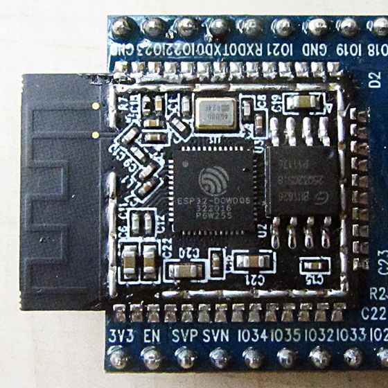
Figure 1. ESP32 WROOM module (example from the web)
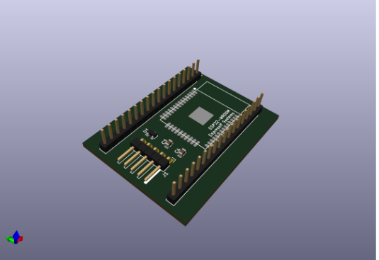
Figure 2. Illustration of PCB board for ESP32 in the context of Alvin robot
Main component B: Alvin artificial intelligence controls ESP controller from mobile deviceActual "brains" of four wheeled robot (car) will be inside of Alvin AI engine. Alvin AI is mobile application, so four wheeled robot will needt to be equipped stand for smartphone.
Alvin has a limited AI engine and school students will teach alvin AI four wheeled robot by teaching AI. AI is combined with machine vision, so AI has actually "eyes" in the situation and can recognize objects and structures
So, in practise, students program Alvin Artificial Intelligence to respond to measurements sent by a robot or IoT device or machine vision algorithm (in mobile phone). For example, Alvin can say or display something and control the robot based on student’s programming.
Main Component C: Machine visionto be extended :)
Body of the Car and related partsWheels will be 3D-printed and body of the car will be lasercutted. From the electronics perspective ESP32 module will be used to communicate with sensors, motors and mobile phone (artificial intelligence and machine vision)
Where will come from?
Don't understand. I will answer this later on :)
How much will they cost?
Original aim of the robot arm project is to push costs smaller than 10 dollars per robot. I will try to follow same scheme in my remix-project. However, covid-19 crisis is causing a lot of problems for that. Maybe I have to continue after Fab Academy with that.
What parts and systems will be made?
Wheels will be 3D printed, body will be lasercutted, circuit board(s) will be milled and components soldered (ESP32, ultrasound sensor etc.)
What processes will be used?
Laser cutting, 3D printing, vinyl cutting, milling, soldering, 3D design (drawings will be shared in the robot community)
What questions need to be answered?
a lot. I have used our Fab Lab daily meeting to ask some questions. Most difficult thing is to isolation at the home, I have a lot of responsibilities related to covid 19 crisis and digital education. Its difficult to get time for this.
How will it be evaluated?
Feasibility of the project from K-12 students perspective Affordability of the costs etc.
Page menu
under development